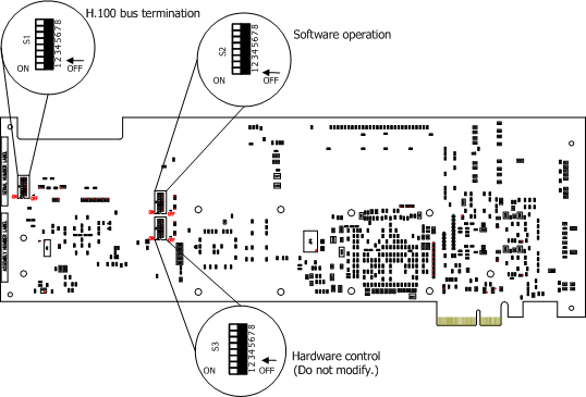
TX 5000E boards contain three DIP switches that are used to configure H.100 bus termination, configure the software operation of the board, and control the hardware-level behavior of the board. The following illustration shows the default DIP switch settings (all switches off) for a TX 5000E board:
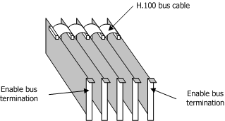
TX 5000E boards connect to an H.100 bus. Boards on the H.100 bus are connected to one another with an H.100 bus cable. The two boards located at either end of the bus must have bus termination enabled, as shown in the following illustration:
DIP switch S1 controls the H.100 bus termination. By default, all S1 switches are set to the OFF position (H.100 bus termination disabled). To enable H.100 bus termination, set all S1 switches to the ON position only for the boards that are on the ends of the H.100 bus.
Note: The switches in the S1 DIP switch must be set to either all ON or all OFF.
DIP switch S2 controls the operation of the software stored on the board's FLASH memory. By default, all S2 switches are set to the OFF position. The following table describes the S2 switches:
|
S2 switch |
Description |
|
1 |
Boot with original image. Set this switch to ON to boot the board to the original software image instead of using the current production software image. This allows for recovery from any condition that resulted in the corruption of the production software image. After setting this switch to ON, use txreset to boot the backup software image, and then use txflash to burn a clean copy of the production image. Once the production image is completely transferred to the board's flash memory, turn this switch to OFF, and issue txreset to boot the board using the newly loaded production software image. |
|
2 |
Override Ethernet 3. Set this switch to ON to:
The TX board has two types of heartbeat indicators:
These indications display on the internal LEDs but can be difficult to view when the board is installed. The DIP switch provides a way to view this information externally. To see an illustration of the Ethernet connectors, refer to Connectors and cables. |
|
3 |
Override Ethernet 1 and Ethernet 2. Set this switch to ON to:
The TX board has four internal LEDs for indicating certain types of error conditions detected by the TX operating system. These error indications include:
These indications display on the internal LEDs but can be difficult to view when the board is installed. The DIP switch provides a way to view this information externally. For deployments that do not require the use of the Ethernet 1 and Ethernet 2 connectors (such as a TDM-based installation that is not using IP signaling), set DIP 3 ON to view error indicator LEDs on these Ethernet connectors. To see an illustration of the Ethernet connectors, refer to Connectors and cables. |
|
4 |
Override trunk connector LED. Set this switch to ON to:
The TX board has four internal LEDs for indicating certain types of error conditions detected by the TX operating system. These error indications include:
These indications display on the internal LEDs but can be difficult to view when the board is installed. The DIP switch provides a way to view this information externally. For deployments that do not require use of the two trunk connectors (such as an IP signaling installation that is not using TDM trunks), set DIP 4 ON to view error indicator LEDs on these trunk connectors. |
|
5 |
Reserved for future use. |
|
6 |
Reserved for future use. |
|
7 |
Reserved for future use. |
|
8 |
Reserved for future use. |
DIP switch S3 controls the hardware-level behavior of the board and is used during the manufacturing process. By default, all S3 switches are set to the OFF position. Do not modify any S3 DIP switch settings.